Linear motors from FAULHABER - Force with direction
A linear motor produces a translational motion, meaning it deploys its force in a straight line. Small linear motors from FAULHABER do this particularly quickly, efficiently and flexibly. They are also characterized by their very high repeatability. This makes them ideal for tasks where components are continuously moved at high speed on a straight axis or where a defined pressure is exerted.
The conventional electric motor generates its force from a rotational motion; its rotor and stator are positioned in a circular arrangement. In contrast, the linear motor has a forcer rod rather than a rotor as its moving component. Its forcer rod and stator are virtually "rolled out" and placed on top of each other in their straight form. As a result, with a linear motor, the torque is produced in a straight line and the forcer rod moves back and forth along one axis.
How are FAULHABER linear motors designed?
In linear motors, the winding can be either the stator or the rotor. The permanent magnets each act as the corresponding counterpart. However, with FAULHABER, the neodymium permanent magnets are always housed in the forcer rod, while the coil acts exclusively as the stator. This design enables small linear motors with a particularly small volume that can also produce a very high torque.
The oblong-shaped winding of the linear motor is self-supporting and coreless so that no cogging torque is generated. It is split into three electrically isolated segments and is hollow inside. In this cavity is where the forcer rod moves; the two components are separated by a small air gap. In the forcer rod, multiple magnets are glued behind one another in a rod shape, with the matching poles meeting in each case (north-north, south-south).
The forcer rod is the only moving component of the linear motor. It has a lubrication-free sleeve bearing made of wear-resistant polymer at each end of the stator. This design is the basis for the extremely long service life of the linear motors from FAULHABER: Depending on the type of load that is moved in the application, they can perform between several million and several hundred million cycles.
How does a small linear motor from FAULHABER work?
In principle, the linear motor is built like a brushless motor. However, in this case, the conductive winding and the permanent-magnetic forcer rod (instead of the rotor) are arranged in a straight line rather than in a circle.
As with the brushless motor, the control electronics direct the flow of current through the segments of the winding to produce a traveling magnetic field. The attracting and repelling forces of this magnetic field affect the magnetic poles of the forcer rod. In this way, they transfer the movement of the traveling field to the forcer rod and produce a powerful torque. The biggest model provides a continuous force of 9.2 N.
Three analog Hall sensors detect the position of the forcer rod magnets. Based on these signals, the segments are controlled using three sinusoidal signals that are each phase-shifted by 120 degrees. The sinusoidal signal can be divided into up to 4096 increments, which enables a high resolution and precise positioning.
The commutation of the winding segments is purely electronic. In conjunction with the freely moving forcer rod, it enables extremely fast acceleration in both directions and accordingly fast direction changes. Linear motors from FAULHABER reach speeds of up to 3.4 m/s.
In this tutorial, the FAULHABER experts guide you in four steps through the important parameters to distinguish when looking for the right linear motor for an application.
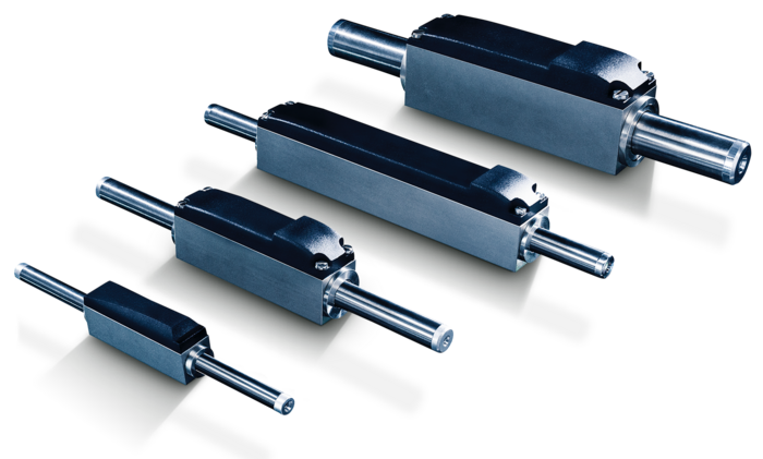
The motors are available in four sizes, from 33 x 8 mm to 74 x 20 mm (L x W), with a wide range of different forcer rod lengths. With the series products, you can choose a stroke length between 15 and 220 mm. Upon request, special designs are also possible.
The Motion Controllers from FAULHABER use the signals of the Hall sensors that are integrated into the PCBs of the linear motors. For other Motion Controllers that require sin/cos signals, product variants with accordingly modified PCBs are available.
Linear motor or linear actuator?
Small linear motors are primarily used in applications where the dynamics of a rotating motor are not sufficient to achieve the fast linear movement required. In addition to their incredibly high dynamics, their very long service life without maintenance is one of the outstanding strengths of the linear motors from FAULHABER. If these are the crucial criteria, using a linear motor is generally the optimal solution.
A linear movement can also be produced using a rotating motor. Its rotational force is then translated into a linear action through transmission elements such as belts, chains or lead screws. This mechanism is described as a linear actuator. If a very high torque or particularly high precision is required, linear actuators with a gearhead or with a direct drive may be suitable as a drive solution.
Typical applications for small linear motors
Linear motors from FAULHABER can be used to replace pneumatic systems in positioning tasks. They are also particularly well suited for micro-positioning tasks, for example in optics. The drives are also ideal for straight movements in pick-and-place applications. Their high dynamics make it possible to maximize the machine throughout, while their extremely long service life helps to minimize maintenance costs. In general, the same applies to similar applications in factory automation and robotics or in metrology and testing. Linear motors are also ideal for use in aerospace applications thanks to their long service life and the almost zero-maintenance they require.
A capsule full of material samples on its way back to Earth. Exposed to centrifugal forces of up to 12 G and temperatures from -270 to 5,000 degrees Celsius at its shell. The capsule has to brave it all to bring back an answer to an existential question: What is the origin of life on...
Modern microscopes have become an indispensable part of medical research. The procedure for quickly and precisely examining the relevant sections of a sample has always been to adjust the slide’s position by moving the stage under the lens. But thanks to technological advancements,...
In this webinar you will learn a simple way to estimate the motor temperature in continuous operation, see the temperature effect, improve motor performance in terms of torque and speed, and select a motor for an application with power dissipation in mind.
Here you will find external YouTube contents for the article. Click to watch.
I consent to being shown external contents. I am aware that personal data may be shared with third-party platforms. For more information, refer to our privacy policy.