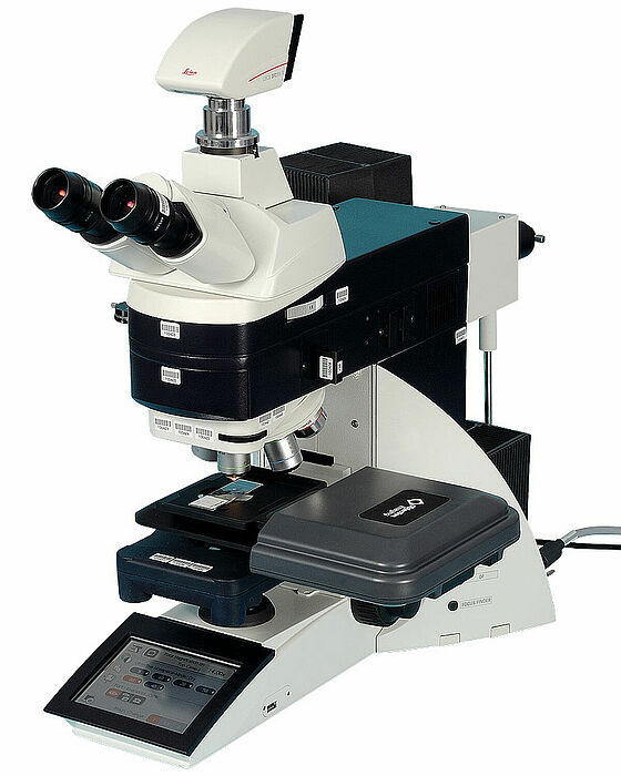
The more we focus on one point, the more limited our field of vision becomes. This particularly applies to modern microscopes with their high levels of magnification. In order to evaluate a sample entirely and not just at select points, the sample needs to be systematically moved while remaining in focus. Objective Imaging Ltd in Cambridge has developed its new OASIS Glide Scanning Stage to meet the requirements of modern microscope techniques. The moveable stage uses the latest drive technology from microdrive specialist FAULHABER based in Schönaich near Stuttgart. The direct-drive linear motor sets new standards in flexibility and precision.
Expanding the field of vision.
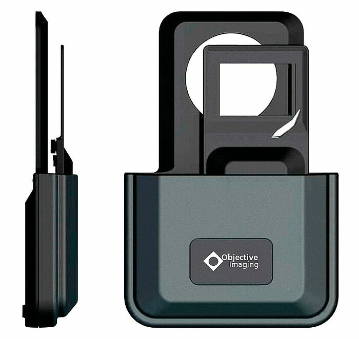
The OASIS Glide-S1 works with an “adjustment window” of 75 x 52 mm. The new linear drives offer previously unattainable precision and speed, as well as boasting the ultimate in smooth operation. The latter was an important criterion in choosing this drive system. Mechanical play, such as that seen in lead screw drives, is eliminated. Along with its advanced technology, the stage also offers standard features such as a dovetail guide and screw fastening suitable for the majority of microscopes. A new manual entry unit with color touchscreen and 3-axis joystick greatly simplifies adjustments for various positions. Compared to previous systems, the new stage comes with superior mechanical specifications despite being smaller and lighter. Mechanical play is almost completely eliminated by the drive as is operational noise. Exceptional vertical stability and lack of vibration accommodate the improved resolution at higher progression speeds. The entire system does not require any maintenance and is easy to equip.
At the heart of the adjustable stage are two linear motors with +/- 30 and +/- 80 mm strokes that work together in concert. Along with considerably better mechanical resolution, this drive solution also represents better value compared to traditional drive solutions in this segment.
Compact linear technology
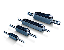
The linear drive combines the quick and easy control of an electrical system with the simple construction of pneumatic cylinders. Instead of the usual “surface rotor” with slides and guides, the microdrive is built within a new, rotationally symmetric design of the rotor. The rectangular, easily flange-mounted stator is designed for close to universal fit and can therefore be easily integrated with the scanning stage. The slimline design also benefits from the fact that the stator (motor) measures only 12.5 x 19.9 x 49.4 mm (W x H x L), including the plug connector (Image 3). The forcer rod is currently offered in six variations, each with a diameter of 6.3 mm and selectable lengths of 82, 109, 127, 154, 172 and 190 mm. This makes stroke lengths of up to +/- 10, 20, 30, 40, 50 and even 60 mm possible, or to put it another way: the forcer rods can be used for applications with lengths ranging from 20 up to 120 mm. Impressively, the motors only weigh between 57 and 82 g.
From the user’s perspective, the drive consists of only three individual pieces: the stator (motor), the plug with cable and the forcer rod. A non-magnetic steel case holds the self-supporting three-phase AC coil winding as well as the rotor’s sleeve mounting made of special plain bearing material. The connector plug and a printed circuit board for three Hall sensors, which are used for positioning, are hidden under the upper cover. The precision sliding metal rod, which refers to the forcer rod, is equipped with super-strong permanent magnets.
The mechanical properties of the linear DC-Servomotor are impressive: the continuous force of the rod amounts to 3.6 N, with a peak or strike force of up to 10.7 N available. Depending on the stress scenario, the acceleration for the 20 mm version equates to 198 m/s², in other words 19 times faster than gravitational acceleration, while the 120 mm version manages 82.9 m/s². The robust plain bearings for the forcer rod smoothly accommodate speeds up to 3.2 m/s. The permitted operational temperature range spans from -20 to +125 °C, covering all of the usual application areas. Despite these outstanding performance figures, the linear motor is precisely adjustable using the motion controller. Repeat accuracy (maximum deviation during multiple repeated movements) amounts to 40 µm. The three linear Hall sensors in combination with the motion controller limit the maximum positioning margin of error, meaning the difference between predefined and measured position of the system, to 120 µm for the 20 mm version and up to 220 µm for the 120 mm model.
Since all values are determined purely electrically, mechanical tolerances, wear and thermal expansion of the components are of no relevance.
Products


