Zinc protects steel against rust. Vehicle manufacturers therefore mainly use zinc-plated sheet metal for vehicle bodies. Previously, the protective metallic coating was applied by means of electroplating. However, hot-dip galvanisation is now becoming the method of choice. It provides even better corrosion protection. When such hot-dip galvanised metal sheets were first used in production, an unexpected problem arose during soldering.
Soldering or welding?
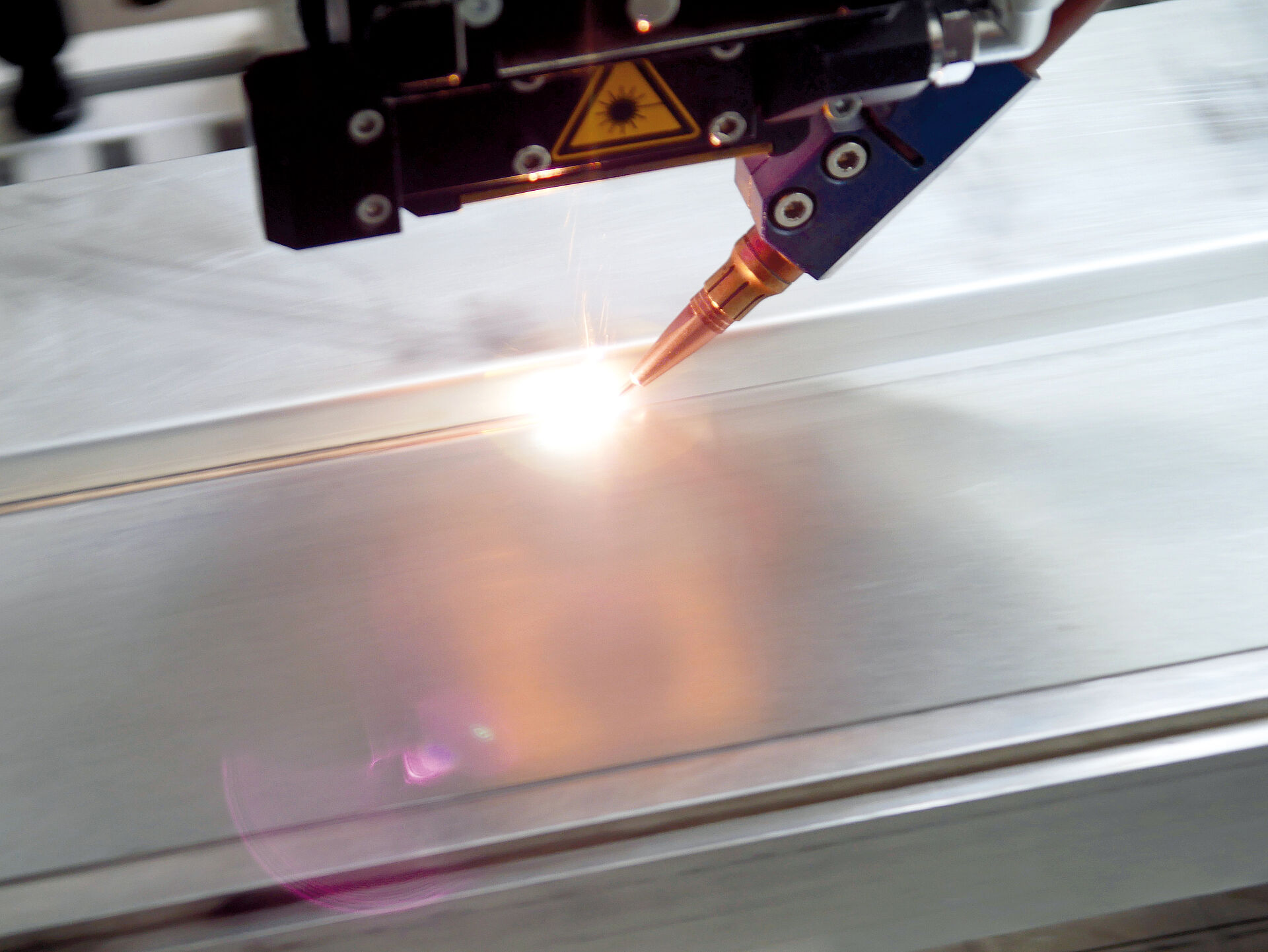
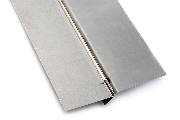
Compared to welding, soldering offers a series of advantages for series production in the automotive industry. In the case of welding, the metal sheets are heated to melting temperature along the welding seam itself and the two sheets are then directly joined together. This requires a high degree of precision and it is not possible to achieve visible seam quality. Welded seams are rough and the vaporisation of zinc makes them porous. With soldering, however, a seam made of a different material is inserted as a filler material between the metal sheets. This coppersilicon solder – liquefies during soldering and then solidifies again – not only joins the parts together, but also fills the gap between them. As a result, soldering permits a greater dimensional tolerance and requires less effort with regard to clamping the workpieces. Above all, soldering allows gap-free joints to be made in visible quality, which means that the soldered components can then be painted without first having to undergo further processing.
In the case of hot-dip galvanised metal sheets, however, the solder does not behave in the usual way. "On the surfaces next to the seam there was increased spatter from liquid solder. Microspatter in particular occurred which is hard to see initially, but then becomes clearly visible after painting", reports Dr. Axel Luft, Automotive Sales Manager at Laserline. "There was also a deterioration in the quality of the actual seam. It was rougher and often formed socalled wavelets, in the other words points at which the solder crosses the planned seam boundary."
Soldering solution for hot-dip galvanised metal sheets
It was obvious that these problems had something to do with the zinc layer on the steel sheet. As a result of the hot-dip galvanisation, this layer had become thicker and less regular. Furthermore, it exhibited a different reflection behaviour, which also had a negative effect on the soldering process. Thorge Hammer, who as an engineer in the technology planning and development department at Volkswagen in Wolfsburg is responsible for this soldering process, had an idea how to solve this problem: The zinc should be removed from the edges of the seam before soldering takes place. However, this would require the usual circular laser spot to be rectangular and would also have to have an opening through which the solder can be fed. The "front" corners of the spot would then be responsible for removing the zinc, while the larger part of the rectangle performs the actual soldering.
"From a technical viewpoint, this solution was not possible, but we were on the right track", recalls Dr. Markus Baumann, chief development engineer at Laserline. "Instead of forming a spot with a complex – and therefore optically very difficult – shape, we finally added two smaller spots to the main spot. During soldering, these smaller spots are always directed at the edges of the seam in front of the main spot which measures a few square millimetres." Their energy is enough to vaporise the zinc layer in this area, to start to melt the steel and to generate slight oxidation. This produces a so-called passive layer that prevents sloshing of the solder liquefied by the main spot.
As a result, the soldered parts do not require subsequent work to remove solder spatter before painting. There is another reason why the rectangular main spot proved to be a good solution: It distributes heat over the solder more evenly than its circular counterpart, which also contributes to a calmer solder bath. "With this technology, we were finally able to solve all of the problems that we encountered with hot-dip galvanised metal sheets." says a delighted Dr. Luft. "It is now used in series production at VW. And it allows us to achieve a soldering speed of up to 4.5 metres per minute. Other manufacturers will follow soon."
Beam splitting with optics module
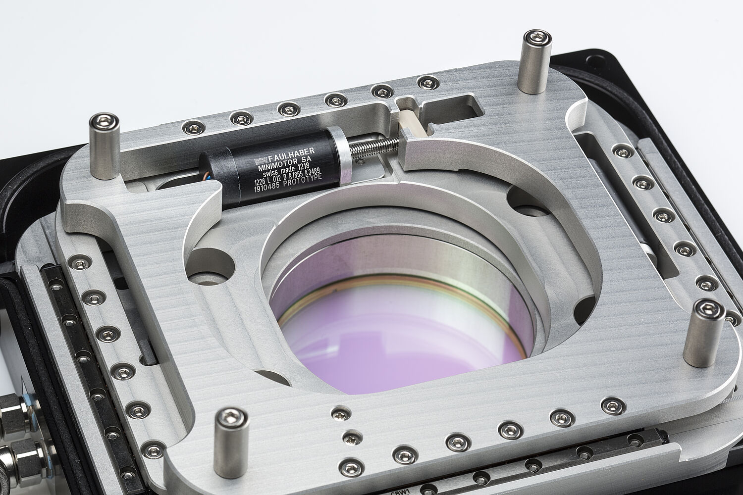
An optics module is responsible for ensuring precise alignment of the spots. It contains various optical elements that selectively modify the laser beam. The collimation lens aligns the divergent laser beams leaving the fibre-optic cable, so that they run parallel to each other. A so-called homogenisation array generates a square-shaped main spot, while other optical elements split the beam and generate additional spots. In the case of soldering, two leading spots are generated to the front and side of the main spot. To obtain the desired clean seam at the end of the process, the power distribution between the main and leading spots as well as between the leading spots must be precisely set. How the laser power is distributed to these spots depends on the position of the optical elements. By moving these elements in the x and y-axis, it is possible to achieve the precise distribution of laser power required for the task in question.
To deep-weld aluminium, for example, a small, intensive spot can be positioned inside the weaker large spot. To weld together metal sheets of different thicknesses, two spots can be adapted to the respective material. This can be done during the running process because the elements in the Laserline optics module are moved by motors.
The edge length of this square-shaped module is 12 centimetres, with a depth of 5 centimetres. The optical elements and a sophisticated mechanical system are housed in this small space. There isn't much room left for the motors. The primary requirement placed on the drives is therefore compactness.
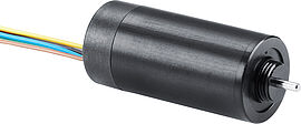
"We opted for brushless DC-servomotors of the 1226 B FAULHABER series with 12 millimetre diameter, with lead screws bonded directly to the motor shaft and without shaft coupling", explains Dr. Baumann. "This provides us a very compact drive which nevertheless reliably delivers the required power and speed. Easy integration of the motor controller in the system was another important consideration." The Motion Controller from FAULHABER was housed outside of the module and communicates by means of an RS232 serial interface. If the Laserline customer so desires, the motor/controller combination can also be actuated via a CAN bus system without needing to make any changes to the mechanics or housing. The RS232 controller can easily be replaced with a version with CANopen interface.
Motor with position guarantee
The laser optics are mounted to a robot arm during soldering and welding; this robot arm moves the laser optics to the required position. The optics must withstand considerable dynamic loads which act on the motors and which can trigger unwanted changes in position. "This is no problem for the FAULHABER motor because it detects its current position using the integrated Hall sensor and if necessary readjusts – at the latest when the laser is positioned on the seam", emphasises Dr. Luft. "This gives us the certainty that any incorrect positioning is ruled out. Thanks to the high quality of the drives, we can rely on consistently reproducible results. This is crucial because our customers expect trouble-free operation over a period of at least seven years!"
For Dr. Baumann it was clear that he would find the right motor at FAULHABER – just as he did eight years ago when looking for the right motor for a new zoom optics system. Back then, stepper motors were generally used for this type of device. However, as the development engineer reports, these stepper motors had problems with the acceleration of masses in the robot arm: "The dynamic load can cause a stepper motor to miss out individual steps. To prevent this from happening, an encoder can additionally be used for position determination and readjustment. This is not only complicated but in this combination it is also expensive. When I was younger, I needed a compact motor for a model ship and I found it at FAULHABER. I remembered this when developing the zoom optics system, contacted FAULHABER and once again found the optimum drive. This has helped us create an extremely cost-effective solution that has since proven very successful." The new multispot module too carries out its work in series production flawlessly. Furthermore, this optical system has already gained widespread recognition among experts: The technical solution and the economic efficiency achieved in industrial applications over just a short period of time convinced the international jury of the "Innovation Award Laser Technology". This year, it awarded the developer team first prize.
Products


