In the 1920s, it was the conflict between the already established electric drive technology in urban traffic and the emerging telecommunications sector that led to the development of radio interference suppression, a sub-concept of EMC. Today, electric drives are usually controlled. In addition to the energy conversion, they also contain the telecommunication components required by the sensors for data transmission. Due to the interference emitted during energy conversion, it is important to ensure the necessary interference resistance of the sensors and telecommunications – often in the smallest of spaces.
Certification in the application
The limit values for controlled electric drives for both emitted interference and for interference resistance are today defined in EN 61800-3.The standard does, however, serve only as a basis for evaluating a drive that is ready for operation. How this behaves in the end device cannot be reliably predicted. Here, the user is obliged to obtain the certification that is valid for his application. In systems with electric miniature drives, the electrical energy is usually transformed
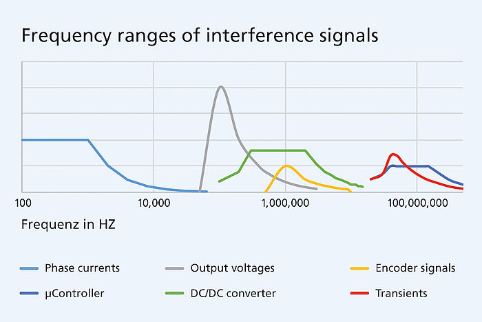
several times. Alternating electrical quantities arise here as voltages and currents with widely varied frequencies, e.g., switching operations in the output stage, (electro)magnetic interference fields during dynamic operation or voltage fluctuations (ripple) when the drives switch.
While EMC directive 2014/30/EU applies to devices in the European single market, concrete evaluation is performed based on the so-called harmonized standards. Compliance with the EMC directive as indicated by the CE marking is required. But devices that are not placed on the European single market or that are intended for industrial re-users also often require proof of compliance. Here, generic standards EN 61000-4-x and EN 61000-6-x are used; which applies depends on whether the devices are intended for industrial use or the consumer sector.
Limit values for controlled drives
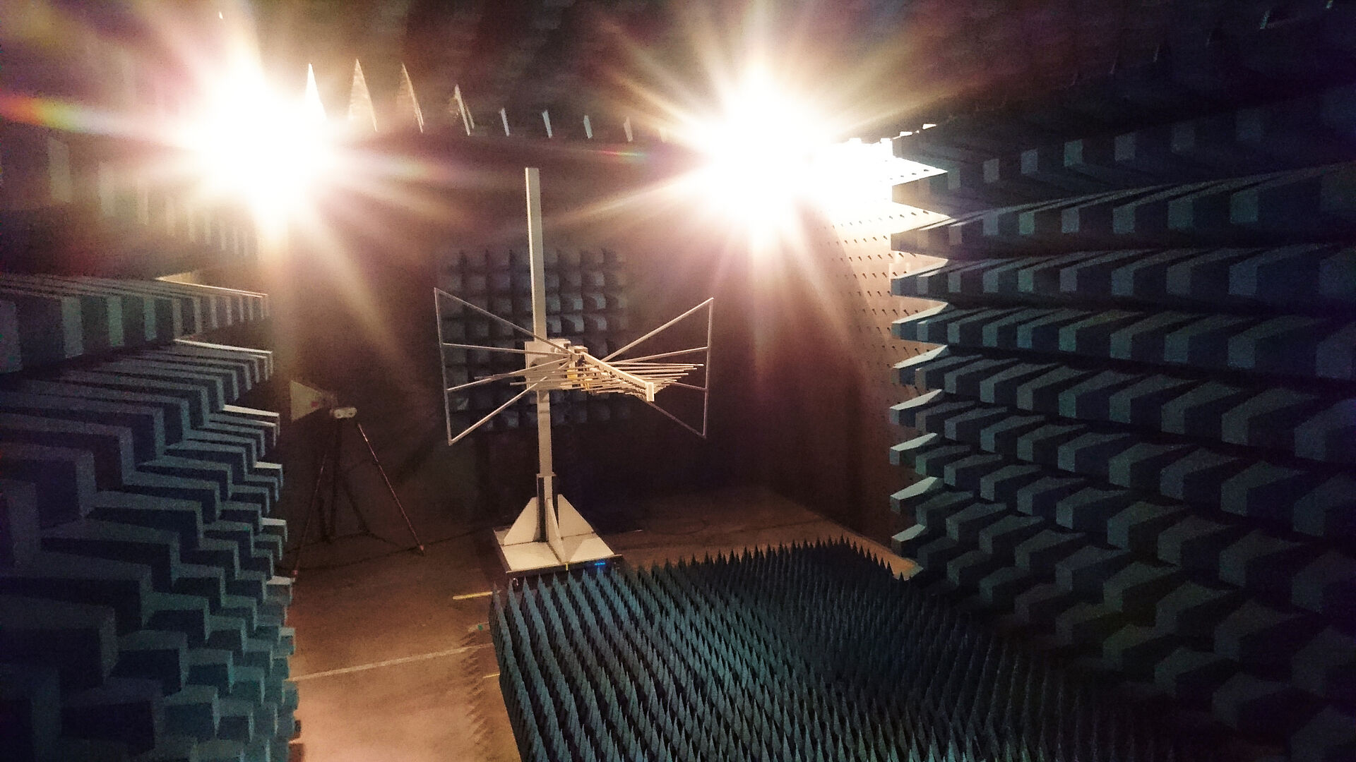
EN 61800-3 serves as the basis for the evaluation of an operationally ready drive consisting of motor and inverter or motion controller operated directly on mains. It also defines the rules for the measurement setup. Various quantifications apply to the types of interference here: In the frequency range from 150 kHz to 30 MHz, they are defined as interference voltage in dB(µV), in the frequency range from 30 MHz to 300 MHz as interference power in dB(pW) and in the range from 30 MHz to 6 GHz as interference field strength in dB(µV/m).
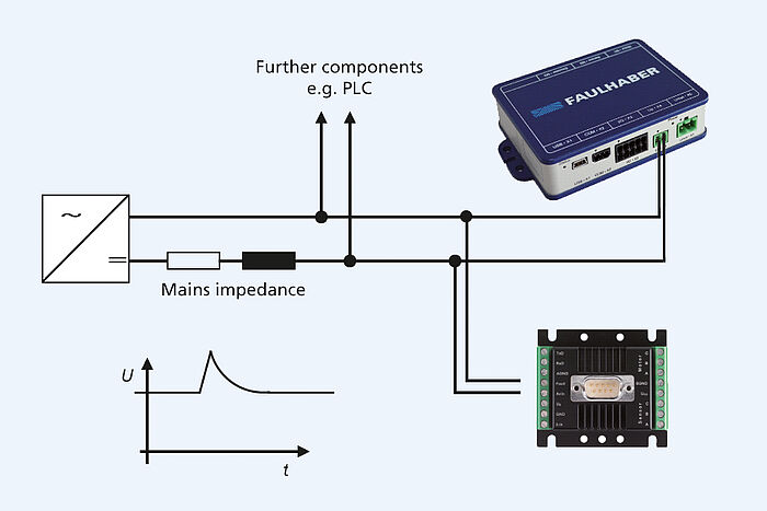
The approach assumes that low-frequency alternating quantities are observed primarily as an interference voltage superimposed on the power supply. The pulsating currents of a controlled drive could then impact, e.g., the operation of a PLC that is connected in parallel. Likewise, a voltage peak in the supply during a braking operation could cause devices that are connected in parallel to initiate a protective shut-down. The interference power and interference field strength, on the other hand, describe the non-cable-borne propagation of electromagnetic fields.
Interference field strength as a challenge
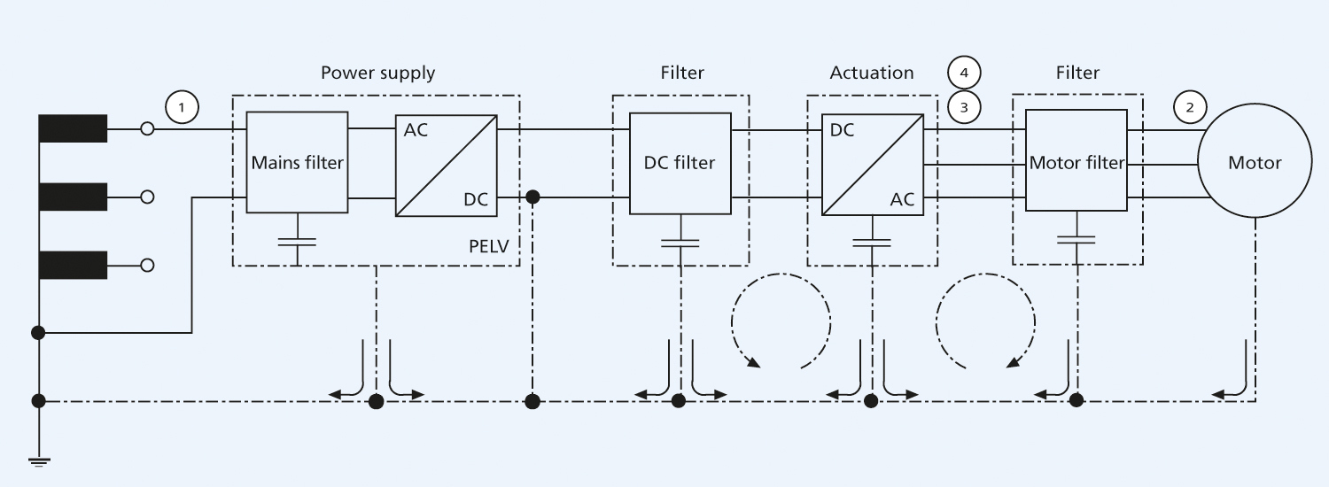
During the certification of a device with integrated miniature drive, the interference field strength is often the greater challenge. Measures that can be taken against it are, e.g., filters on the power outputs for suppressing high-frequency, capacitive interference currents. Each motor supply line must usually also be fully shielded. The same applies for the sensor cable, which is laid separately from the motor supply line. It is also important that all conductive parts be conductively connected to so-called functional earthing using RF shield connectors. Building upon this functional earthing, both ends of the shield can then be connected flat. Pure PE protective earthing is sufficient in only a very small number of cases.
Whereas the interference field strength is effectively attenuated by the functional earthing and the shielded cables, the returning alternating current component in the base plate tends to increase as a result. If these alternating currents flow back to the switching converter via the mains supply or the power supply unit, the AC voltage component on the supply conductor inevitably increases and, thus, so too does the interference voltage. An additional filter is therefore often needed in the supply line that limits the propagation of these currents. It is left to the device manufacturer to decide whether he installs such a filter upstream of each drive – with miniature drives, typically in the 24 V or 48 V supply line – or just upstream of the power supply unit on the AC side. The latter saves costs but functions only if the drives themselves are designed in such a way that they do not mutually interfere with one another.
Interference resistance in the standard tests
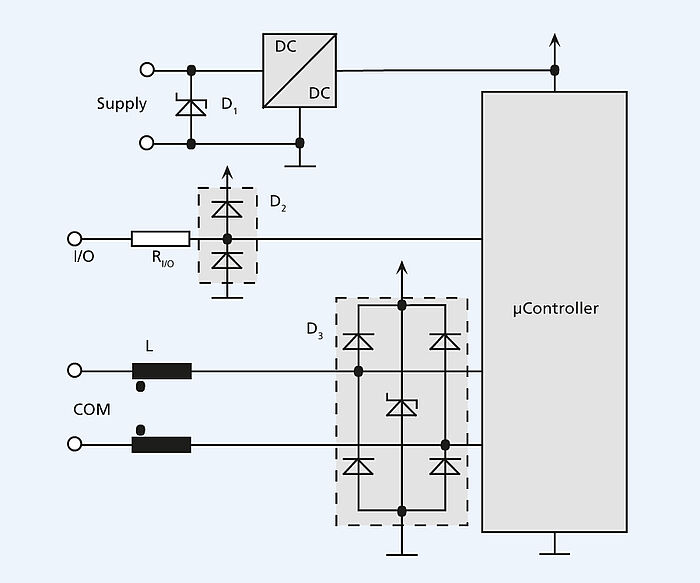
For interference resistance, a wide range of electromagnetic effects are covered by the standard tests, such as interference resistance against electrostatic discharge (ESD) and against high-frequency electromagnetic fields from a neighboring emitter, interference resistance against electrical fast transients (bursts), surges, e.g., caused by lightning, or against RF common-mode interference on longer sensor and communication lines. Additional tests for shorter voltage dips are defined primarily for drives operated directly on the mains network. The typical voltage fluctuations of multiple dynamic drives on a DC system, on the other hand, are not actually detected. For miniature drives, additional interference suppression measures here include using the shortest possible cables or using protective diodes on the supply side. Also possible are ferrite filters, such as are common on analog PC monitor cables or communication cables.
With compact drives, encoders pose the primary challenge for the interference resistance of the components. They must likewise be housed in minimum installation space. Even in small encoders, however, sufficient protection against ESD can be achieved through compact protective elements. The field strengths specified for the interference resistance do not generally pose a problem in either the RF frequency range or in the mains frequency range. Interference resistance against bursts, or fast transients, requires filters on both the supply connections as well as on the signal cables. This does, however, pose a problem on the supply connections because the power supply is typically directly connected to the circuits integrated in the encoder. Effective protection is only possible here in the complete device. Full protection directly in the encoders against standard interference is not generally necessary. If needed, however, a protective diode can be installed, e.g., in an adapter board.
The test signal for conducted RF disturbances acc. to IEC 61000-4-6 is larger than the useful signal of typical encoders. Common mode filters in an encoder for motor diameters of just 20 to 22 mm are not feasible, however. Here, an evaluation must be performed at device level to determine what interference is to be expected. If necessary, the interference resistance can be improved with externally attached ferrites. Voltage dips in the power supply of the drive system can cause the system to shut down. Depending on the buffer of the encoder power supply in the motion controller, the encoder may then likewise be undersupplied in the event of voltage dips. Incremental encoders lose the absolute position information in this case and must be re-referenced.
EMC-compliant design and documentation
EMC for miniature drives is, therefore, anything but trivial for users. This is why the drive specialists at FAULHABER have explored this complex topic in great detail. All motion controllers of the broad range of products comply with current EMC regulations. Not only has the hardware been appropriately optimized, but the documentation has also been redesigned to provide users with the best possible support during the certification of their own devices.
From the contents
- The challenge of EMC:
Interference sources in electric drives, frequency components, radio interference suppression for EMC - CE certification:
EU directives for the operation of electric miniature drives and relevant standards - Emitted interference of devices:
Cable-based interference, coupling paths for electromagnetic disturbances, measurement methods and typical measurement results - Interference signals in controlled drives:
Interference characteristics of a DC-DC converter, interference characteristics of a motor controller - Limitation of emitted interference:
Propagation paths, grounding and shielding, cable routing, filters and measurement results - Interference resistance of devices:
Acceptance criteria, effects, measures - EMC measures for miniature drives:
Integrated motor controllers, externally mounted motor controllers, encoders - Additional measures for increasing robustness:
Coding, complementary signals (line drivers), robustness of various interfaces
